Coarse vertical screen with reverse rake RVGO
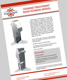
Coarse vertical screen with reverse rake RVGO is designed for preliminary coarse treatment of wastewater from mechanical impurities at sewage pump stations and water treatment facilities of municipal and industrial enterprises. This type of screen is used as part of a mechanical sewage treatment plant and is designed to be installed vertically in a channel. Ideal for installation in deep and wide channels. Most often, RVGO screens perform the function of protecting equipment installed downstream of sewage after RVGO, for example, fine-treatment screens or pumps.

Figure 1. The basic design of RVGO screen
1 – Screen housing; 2 – gear motor; 3 – belt sling; 4 – rake bucket; 5 – filter screen with frame; 6 – cleaner; 7 – rubber sealing apron; 8 – bridge; 9 – protective slide casing; 10 – cover; 11 – side inserts; 12 – winch drum; 13 – screen inlet water level sensor; 14 – supports.
The main carrier of the screen is the screen housing. The screen housing consists of sidewalls made in the form of a seamless profile, the bottom and the upper beams. The sides of the housing are equipped with guides for a filter screen and a rake bucket. The housing is also attached with a threshold, supports, a bucket cleaning unit, a drive with a winch, protective casings and rubber sealing aprons.
The screen housing is installed vertically without a gap at the bottom of the channel and fixed to the channel side by anchors through the fixed supports. The gap between the screen housing and the vertical walls of the channel is covered with rubber sealing aprons. At the bottom of the housing in front of the screen there is a bridge designed to direct large debris above the points where the bucket rakes enter the filter screen.
The filter screen is welded, assembled on its frame from slats of rectangular cross-section, which allows lifting the whole filter screen along the guides over the channel for maintenance during operation. The filter screen does not have transverse stiffening elements in the wastewater stream.
The mechanical impurities trapped in the filter screen are removed from it by a rake bucket - moving along the guides bottom-up the rake bucket removes dirt from the filter screen and lifts it above the channel. Cleaning of the filter screen is carried out from its back side with respect to the flow of sewage, which prevents "pushing" the caught impurities to the side of the purified stream. The bucket rakes completely clear the gap between the slats of the screen and extend beyond its front surface by 200 - 250 mm, which makes it possible to extract large objects trapped in the filter screen from the wastewater.
Cleaning of the bucket from the caught impurities is made by a cleaner that scrapes them from the bucket and rake surface in the upper part of the screen above the channel. The caught impurities are scraped off in front of the grate - to the side above the untreated sewage stream. Further, the waste directed by the protective slide housing is fed to the conveying device or to the refuse receptacle.
After cleaning, the bucket remains in its upper position until a signal is received from the grid inlet water level sensor or a configurable timer (whichever comes earlier). When the signal is received, the bucket begins to go down from the top and in the lower position (at the bottom of the channel), its rakes pass through the bar spacings of the filter screen and then the filter screen cleaning cycle begins again. The operation cycles of the RVGO screen are shown in Fig. 2.

Figure 2. RVGO screen operation cycle
The rake bucket moves up- and downwards along the guides by winding onto the power winch a belt sling with one end fixed to the winch drum and the other end to the bucket. The bucket contact with the guides is carried out through special slides made of high-quality wear-resistant polymer material ZEDEX.
Above the channel, all moving elements of the screen are covered with protective casings, side inserts and a protective slide casing.
The screen is equipped and supplied with an automatic control system – a control cabinet, remote control, ultrasonic level sensor, and the drive stopping proximity sensors. The control system ensures both manual and automatic operation of the screen, as well as protection against abnormal operating modes by disconnecting the drive power and giving an emergency light signal. In order to reduce the wear and tear of the drive mechanisms in the control system, a smooth start-up is provided by the frequency converter.
All parts and components of the RVGO screen, which are in contact with water and trapped impurities, are standardly made of AISI 304 stainless steel (optionally AISI 316).
Customization of RVGO screens with non-standard dimensions and technical specifications is possible according to the Customer requirements after preliminary study of the design and coordination of methods of transportation, installation and other technical conditions.
Examples of the most common installation options of RVGO screens are shown in Figure 3.

Figure 3. The most common installation options of RVGO screens
RVGO screens installed into very deep channels consist of several sections – the lower, upper and intermediate one. At the installation site, the sections are installed one upon the other, starting from the bottom, assembled together by bolting and fixed by anchors to the sides or back wall of the channel.
Parameter name | Unit of measurement | Parameter value | |
Rated value of the bar spacing e | mm | 16, 20, 30, 40, 50, 60, 80, 100 | |
Channel width B | minimum | mm | 500 |
maximum | unlimited | ||
Channel depth H | minimum | mm | 1000 |
maximum | unlimited | ||
Maximum channel water level H3 | mm | 2400 | |
Dump height h | mm | 850 - 2500 | |
Overall screen width above the channel S: | mm | 1780 | |
Power supply | V/Hz | 380 / 50 | |
Drive rated power | kW | 1.1 | |
Climatic category according to GOST 15150 | - | UKhL4 (boreal climate 4) | |
Standard screen designs are combined in a size range, with the following variable parameters shown in Figure 4:
Bar spacing (e) – the distance between the slats;
Width (B) – rated width of the channel;
Depth (H) – rated depth of the channel;
Dump height (h).

Figure 4. RVGO screen dimensions
The screen is installed through the pivot supports on the ribs of the channel, so that it can be mounted without emptying the channel. The rotary supports also allow setting the screen in a horizontal position above the channel for maintenance purposes.
- Cleaning the screen from the clean to the dirty side, unloading the collected wastes to the dirty side, the possibility of removing large objects from the sewage.
- The rake bucket moves up- and downwards along the guides by winding a belt sling onto the power winch.
- Ideal for deep and wide channels.
- Possibility of lifting the filter screen above the channel without dismantling the screen.
- Fully automated.


