Fine screen with perforated plates
The screen is designed for fine treatment of wastewater at sewage treatment facilities of municipal and industrial enterprises from mechanical impurities larger than than the size of the screen holes.
The screen is made of corrosion-resistant steel and consists of a welded frame (frame) (1) mounted on rotary supports (2), a filter screen and attachable equipment. The filter screen is an infinite filtering cloth consisting of stepped perforated panels (3). The panels are gimballed on two plate-like roller chains (4) made of corrosion-resistant steel with plastic rollers and driven by a gear motor (5) through the drive shaft (6) and the sprocket (7). The underwater part of the chains runs around non-rotating lower guides (8) made of wear-resistant plastic.

1 - frame; 2 - swivel supports; 3 - perforated panels; 4 - roller chains; 5 - screen drive; 6 - drive shaft; 7 - sprockets; 8 - bottom guides; 9 - belt brush; 10 - cylindrical brush; 11 - nozzles; 12 - brush drive; 13 - adjustment unit; 14 - removable cover; 15 - slide-ways; 16 - rubber scraper; 17 - hatch; 18 - cover; 19 - overlays; 20 - connecting hose; 21 - electromechanical tap; 22 - screen filter; 23 - tap; 24 - hose; 25 - flush manifold.
The gap between the bridge of the screen and the panels is covered with a belt brush made of polymer bristles (9). Moving upwards, the panels take small debris out of the sewage channel. Larger debris is captured and extracted from the channel by panel steps.
In the upper part, the perforated panels are cleaned from the outside by a cylindrical polymer bristle brush (10) rotating in the opposite direction, and on the inside – by the water jets flushing through the flat-jet nozzles (11). The brush is driven by a gear motor (12). The distance between the brush shaft and the filter screen is adjusted by the unit (13).
The brush is closed with a removable casing (14), the lower part of which is a waste discharging slide (15). A rubber scraper (16) is installed in the casing to clean the brush. To access the brush in the casing there is a manhole (17). A rubber scraper (18) is mounted on the screen frame, eliminating the entry of waste removed from the screen back into the channel.
Panels (3) on the back side of the filter screen can be positioned parallel to the flow to reduce the hydraulic resistance and avoid the accumulation of small debris in the screen housing. To reduce wear in the friction areas of the panels, the cover plates (19) made of wear-resistant antifriction plastic are fitted to the screen housing.
Above the level of the channel, the frame is equipped with removable covers (20) servicing the perforated panels of the filter screen.
The shut-off valve of the filter screen washing unit is mounted on a rotary support and consists of an electromechanical tap (21), a coarse strainer (22), a mechanical tap (23) and a flexible hose with a nozzle (24) for connection to a water pipe. The angle between the jets of water and the panels is regulated by turning the manifold (25) with injectors installed in the frame. The manifold is connected to the stop valve by a flexible sleeve (26).
The screen is equipped with a filter screen washing system and a control system consisting of a ShU-ERPE control cabinet and a VPU-ERPE remote control panel.
The screen is transported on a wooden pallet or in a metal transport container, which are removed before use.
The screen can operate in automatic and manual modes.
| Parameter name | Unit of measurement | Value |
|---|---|---|
| Perforation diameter | mm | 2; 3; 4; 6; 8 |
| Channel installation width | mm | 1000 ÷ 2600 |
| Channel installation depth | mm | 1000 ÷ 4000 |
| Maximum channel water level | mm | 3700 |
| Screen installation angle | grad. | 60 |
| Dump height | mm | 850; 1000; 1500 |
| Pressure of rinsing technical water | bar. | 3 ÷ 7 |
Size of inclusions in technical water, no more | mkm. | 250 |
| Instantaneous technical water flow rate*1 | l/min. | 50,6 ÷ 151,8 |
| Power supply | V/Hz | 380/50 |
| Drive rated power | kW | 0,55; 0,75; 1,1 |
| Main drive protection degree to GOST 14254 | - | IP55; IP66 |
| Rated brush drive power | kW | 1,1; 1,5; 1,8; 2,2 |
| Brush drive protection degree to GOST 14254 | - | IP55; IP66 |
Control system protection degree to GOST 14254 | - | IP54; IP65 |
| Climatic category according to GOST 15150 | - | UKhL4 (boreal climate 4) |
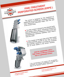
- Ideal for wastewater with a high content of fibrous inclusions due to a perforated screen.
- The filter screen is formed by the stepped perforated panels, which allows increasing productivity, reducing the hydraulic resistance of the screen and simultaneously removing relatively large objects from the water.
- Step panels on the back side of the filter screen can be positioned parallel to the flow to reduce the hydraulic resistance and avoid the accumulation of small debris in the screen housing.


